I recently had my entire chassis replaced from the old rusty mess I had to a nice shiny, galvanised one.
As with most Land Rover owners who have just paid out for significant work that they didn’t do themselves, I started poking around underneath to both admire the result and to look for snagging work I needed to pick up. In doing so, I discovered something that maybe a few Defender owners are not really aware of.
My previous car was a CSW edition out of the factory meaning it had side windows, carpets and seats in the back but was otherwise the same as a hard top. Or so I thought!
It turns out there were a few other little tweaks to aid with sound proofing. One of these is the mudshield behind the front wheel. Go look at the back of your front wheel arch and see if it looks like this….
Other than the CSW edition, all Defenders chuck mud up onto the outrigger and are slowly dissolving their footwells. This is what eventually led me to admit I needed a new chassis. I could really do with this not happening again.
There is a great company you need to know about called Gwyn Lewis 4×4. I have no relationship with the mother than loving this simple but effective product – the mud shield. It is a plastic panel you screw in-place and it reduces road noise (a little) but mainly prevents mud being flung up to where it causes havoc.
That looks better doesn’t it. Worth the £30? I think so.
They also do panels for the other arches, but for me this is the place where these parts are essential. Don’t wait until your chassis has eaten itself.
As I’m having trouble with my TD5 Defender “kangarooing” under hard acceleration, I did a bit of googling and asked questions on the usual forums. The kangarooing is apparently a known issue caused by either:
injector seals being worn
injector harness has oil in it
MAF sensor issues
Fuel regulator fault
Fuel pump fault
Well the pump was whining like a randy mosquito, so that got swapped, the injector harness swapped and the injector seals replaced. The red plug (C0158) at the ECU was removed, cleaned and replaced. No oil visible in there but worth a look. The turbo wastegate actuator was rusty, so I had that replaced when the car went in for MOT, thinking the garage can test the boost better than I can.
Still has the problem.
MAF disconnected next. Went for a drive and saw no difference. MAF was getting power. Maybe it was duff. New MAF, no difference.
I invested in a (budget) diagnostics tool from iCarsoft i930 to read what was going on. The Engine warning light isn’t coming on, so it isn’t anything the ECU is too concerned about, but I want it fixed.
The Error codes were:
Manifold pressure circuit fault logged low
Inlet air temp circuit fault. logged low
Multiplex input circuit fault logged low
1% reference voltage fault logged low
Driver demand 3 fault logged low
Manifold pressure reads as 42.75kPa and Ambient pressure as 0kPa. Science tells us air pressure at sea level is 101.325kPa, so something is weird!
As my TD5 is an early one, the lack of Driver Demand 3 isn’t necessarily a problem. Searching online, suggestions are roughly:
One of the sensors is duff and throwing out everything else
The ECU has in it oil due to the injector harness
The ECU hardness is worn and shorting out
The two sensors dealing with air pressure and temp share a common earth pin at the ECU and the pressure readings obviously require some kind of investigation.
I bit the bullet and replaced both sensors. The MAP/IAT was particularly gunky, so when a previous owner blanked the EGR, they didn’t bother cleaning the manifold or sensor, so I am pleased I swapped it out.
Gunky, due to the EGR which was blanked off long ago, but why blank the EGR and not swap the sensor? Well, because they cost about £100
The pins powering both sensors are live at the ECU and the sensor plugs, errors won’t clear on the iCarsoft and the problem persists.
Visual inspection of the harness indicates it looks sound, but maybe time to rip it out and replace it?
PSI Powerbox
The fact there is a PSI Power box wired into the ECU harness probably isn’t helping. It gives a kick of extra fuel when pulling away, but I have it unplugged for now whilst I diagnose what is going on. The box is a fudge to avoid doing a remap for more power, in combination with a bigger intercooler. My ECU is a “10P” variant, the chip is soldered on and not writable unless it is removed and a socketed one soldered in its place. Using this box avoids that.
As the intercooler in the car is stock, the poor old turbo is going to be working a bit harder than designed and to remove it from the troubleshooting, it is getting unplugged. Maybe once this is resolved and I invest in a new intercooler, I can plug it back in or rip it out entirely and get the proper remap done. But that is all for another day as there is no point remapping a duff engine….
From internet searches, it does seem other people have similar fault codes with the iCarsoft i930 on a pre-2007 Defender, despite the fact the device supports older ones like mine and has a menu option for it on the screen.
So, after mulling this over, I hired a Nanocom.
Nanocom
The Nanocom shows a few alerts, all of which are benign as I don’t have any of these things fitted:
10,1 aircon
10,3 tachometer drive
10,4 gearbox/abs
10,5 aircon clutch
14,1 aircon fan
14,3 tach drive
14,4 gearbox/abs
14,5 aircon
Nothing about the AAP, MAF, multiplexer etc.
There are also two other logged faults. One refers to the EGR being stuck closed (20,5), which is expected as the engine has an EGR blank fitted. The other…..
So a test drive showed the problem:
1.36 bar is a little bit high….
The TD5 engine will boost around 1.2bar with a stock intercooler. 1.4 is where the overboost kicks in. so When my the Nanocom is reading 1.36, it soon trips to 1.4 and the fuelling is cut by the ECU. On the Nanocom, the boost drops immediately to about 0.3, the engine “kangaroos” and the overboost condition is logged. So how do we fix this?
First let’s check the sensors are actually working, because we know the i930 warned they were duff:
They look fine and change as we drive. So sensors are good!
So how to fix the overboost?
There are some gizmos that can fool the ECU to ignore overboost, but the overboost control is there to protect the engine and I’d rather wind it back and make the bouncing go away. The correct way to handle this is to wind out the wastegate rod, making it longer and thus vent the boost pressure earlier. “Longer is lower”.
First I marked where the rod was set to:
Then used a 10mm to undo the lock nut and adjusted the rod so more space showed between the mark and the lock nut.
So what happens now? well, the boost only reaches 1.28 and no “kangarooing”. The Nanocom no longer logs an Overboost. Hooray!
With trial and error, I could wind it back a quarter turn, drive and test it and repeat until I know where the sweet spot is, but I don’t have the time and only hired the Nanocom for a week. I’ll look to buy one in future, but for now, I’m happy enough.
The door hinges on the Land Rover Defender can rust, creak and eventually run too loose to feel like the door is going to swing out forever when you open the door. The good news is, they are really easy to swap.
Buy new hinges and bolts. Paint the hinges using a rattle can of spray paint or some Hammerite. I decided to contrast the hinges against the bodywork black on white. The extra benefit being that black Hammerite is more rust resistant the plain old white enamel. Put a little grease in the turning surfaces and on the pin running through the middle.
These need to go
First-off, have a good look on the inside to see if you can work without removing the door card. Chance are, you can. Otherwise, remove the handles and window winder and pop it off using a trim removal tool. In my case, I was good to leave it in place. Soak the bolts in GT85 and put the kettle on.
Wind down the window. Make life a bit easier when going in and out the car. Put your mug of tea on the wing and get to work.
The trick here is to do them one at a time, starting from the bottom one. Undo the nuts on inside of the door or better still, use a spanner to hold the nut and undo the bolt from the outside. If you have a screw head, go gentle. If you have a torx or hex head, you will be in a better position. Remove just those two bolts and close the door again. You will probably have some shims under the hinge. Keep them and remember where you got them from.
The two bolts in the pillar are secured with metal clips. Undo the bolts and take the hinge off. carefully undo the clip. Clean up the paintwork underneath. Drop on some rustkiller. Install ht new clip. Lose it inside the pillar. Use another clip. realise you’ll be short of clips. Make a fishing kit using some twine and a paperclip to rescue the missing clip. Fix the clip again more tentatively. Step back. Sip some tea.
Rusty old bolts and the hinges are metallic blue. My car was originally Silver and painted white at some point in the past. So, somebody went cheap by using second-hand hinges….
Fit the new hinge to the pillar using new shiny bolts, not forgettign to resue the same number of shims as before. Preferably A4 marine with a torx head. A2 Stainless is an option if you want to save a few pennies. Don’t tighten the hinge up too tight but tight enough so it can help support the door.
Push the two bolts in for the door and carefully open the door, bearing in mind one hinge is carrying the weight. Put the nuts (preferably new nyloc ones) on the other side and tighten them up. Close the door and tighten the pillar bolts. I would go back a half turn or so giving a tiny bit of adjustment potential for when the door settles after the other hinge is in place, but that is up to you.
If the door seems a bit off, remember you have another hinge to do yet and at the moment the door is a bit of a Frankenstein’s monster. If after doing both the door is fighting you, you can revert to the old shims to return the door to a similar fit as the older hinge had. This might be necessary if the door is old and mildly deformed due to wear and tear. New shims are obviously preferred, but you know, Land Rover.
The upper hinges are trickier. Fold the mirror back and undo the door bolts. Remove the nuts but leave the bolts in. Close the door if you had to open it. Having that window open is really rather useful right now.
Undo the pillar bolts and take the hinge off. The mirror will need supporting. Quite obvious but better to be wary than have to buy a new one. Once the hinge is off, remove the pillar clips and anti-rust the body work.
Put the hinge on a flat surface. The ground or a table or one of the seats is better than working on the wing so there is no risk of dropping the mirror. Unbolt the mirror from the hinge. Bolt it onto the new one.
Fir the hinge to the body work, then the door. Tighten it all up and check the door opens and closes OK. Loosen the bolts slightly to get it to settle rather than adjust the striker plate on the door because you’ll be fiddling for hours.
Stand back. Sip tea. Admire handiwork.
So much nicer
Repeat on the other side. Recycle the old bolts and hinges at your local recycling centre.
One of the joys of owning a Land Rover Defender is that you can fix a lot of stuff on it yourself. When it is an old one like my 20yr old 200tdi, you can also turn your hand to improving it, where the original engineers didn’t have the technology or budget at the time. Why Upgrade the wiring?
One key failing of the Defender up to and a little beyond my model is the lack of relays between the battery and the headlights. This generally leads to the headlight switch burning out and will give a dimmer headlight than modern cars. Also, if you upgrade your headlights or bulbs, this modification is pretty much essential.
There is a great little video on YouTube which is a great place to start: BushmanProductionsAU Tutorial, so treat my ramblings here as what I did next after watching it… The Diagram
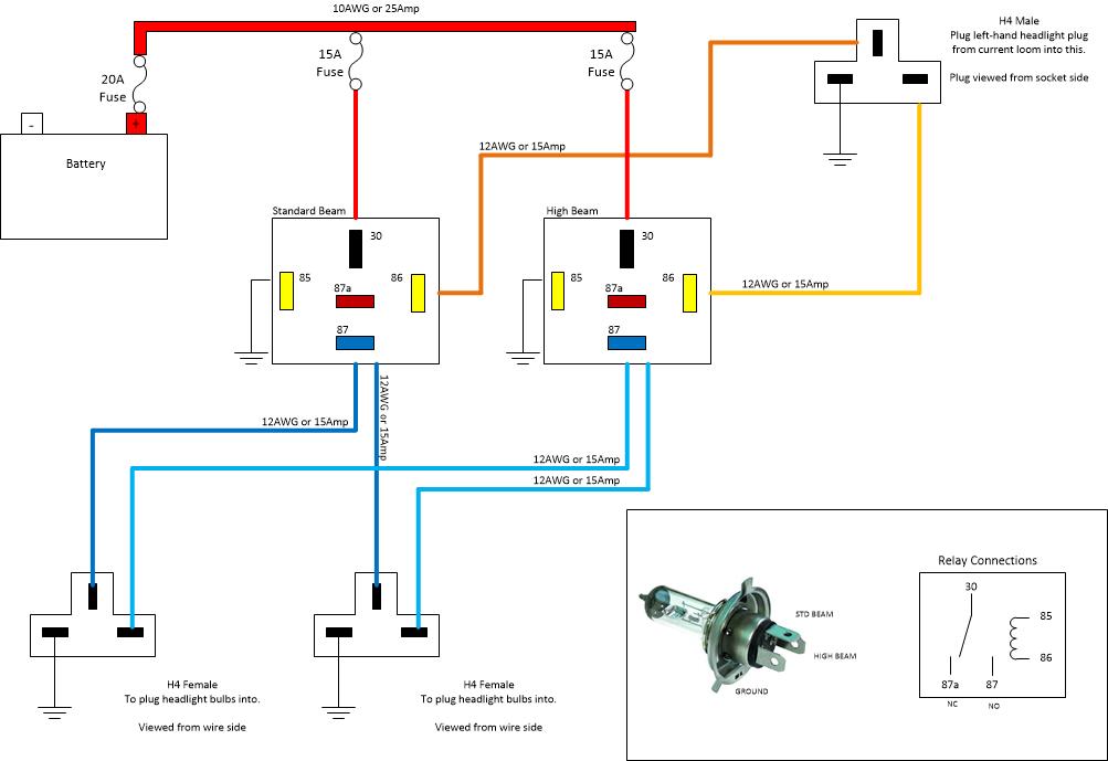
There is a diagram of how I did it, which hopefully makes sense. It purposefully isn’t a wiring schematic using auto-electrical symbols because I expect most people reading this are enthusiasts, not electricians.
Buy What You Need
First thing to get right is not to waste money on a “headlight upgrade kit” because all the bits you need are easy to obtain. I strongly recommend you visit Vehicle Wiring Products to source the stuff you need.
3x in-line fuse holders (or a mini fusebox)
1x 20Amp fuse
2x 15Amp fuses
2x 5-blade changeover relays
2x relay sockets
At least 10 female crimp connectors
Enough red 10AWG/25Amp cable to go from your battery to the relays
Enough 12AWG/15Amp cable to go from your relays to your headlight plug (brown on my diagram)
Same again in a different colour (Yellow on my diagram)
Some 12AWG to earth pin 85 on each relay and third pin on each headlight to a suitable earth (eg. bodywork)
Suitable crimp connectors to connect to your battery
2x H4 female sockets (these go onto the pins on your bulbs)
1x H4 male plug (this takes the pins from one of your existing headlight plugs)
Enough 12AWG to run from your high (full) beam relay to each headlight (pale blue in the diagram)
Same again but a different colour for the standard (dipped) beam
Two blade connectors and a short length of 10AWG (see below)
Enough corrugated plastic shielding to protect all this cable
Enough shrink-fit insulation to do a good job protecting those crimps
8x bullet connectors
2x Double-common snap connectors
Method
The way I recommend doing it is to fit the two relays in the engine bay, attached to the bodyWork. Somewhere just ahead of the washer bottle is fine.
Run cable to each headlight to power them from pin 87 of the relays. Note: you will be running two cables from one pin, so you will have a single crimp connector, a short cable to get clear of the relay pins and then your choice of how to take it from here. I had a mountain of bullet connectors handy, so I put a female crimp on a short bit of cable with a bullet on the other end into a “double-common” bullet connector. Each cable out to a headlight was terminated on a bullet connector and just plugged in. But work out your preferred method and substitute your preferred connector types.
Take a feed from the offside headlight plug itself to pin 86 on each relay. This means you are NOT cutting into your wiring loom, so the fix is 100% removable..
Now wire-up from the battery (with the big in-line fuse in the battery compartment) and out to pin 87a on the relays (via one fuse each, near the relays). This is the fiddly bit! Headlights now always on with sidelights
So, why are the headlights on dipped beam when you turn on the sidelights?
The answer is you have a “dim-dip” system installed. This was a legal requirement from April 1987 until 1988. Land Rover still fitted this system long after that but it is not a legal requirement any more.
All well and good, but what does that mean to us? Inside the nearside wing of your Land Rover is a chunky resister that means when the sidelight circuits are on, some current is passed through the headlights, making them run dim. But, remember we have used a feed from the headlight plug to run some relays. This “dim” voltage is still enough to trip the relays and turn the headlights on full power. We need to disable the dim-dip feature.
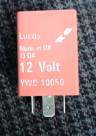
Unscrew the four screws holding on your dashboard instrument panel. Behind the jumble of wires you will see at least two relays. A Yellow one (probably YWB10027L) which stops you leaving the rear heater on when the engine is off and a pink one (YWC10050). This pink one is the troublemaker.
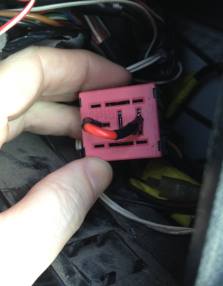
You can pull the relay and your lights will stop working. You can either short the socket or buy a dim-dip bypass relay. I chose to short it. You need some 25Amp cable and two spade connectors. You simply jumper between 87 and 30 as shown here:
Put the dashboard back together and now when you turn-on the sidelights, you will just get sidelights. When you tun on headlights, you will not be dragging two headlights full of current through your control stalk on the steering column.
And now you can upgrade your headlights or just be happy your stock headlights are a little bit brighter.