One of the joys of owning a Land Rover Defender is that you can fix a lot of stuff on it yourself. When it is an old one like my 20yr old 200tdi, you can also turn your hand to improving it, where the original engineers didn’t have the technology or budget at the time.
Why Upgrade the wiring?
One key failing of the Defender up to and a little beyond my model is the lack of relays between the battery and the headlights. This generally leads to the headlight switch burning out and will give a dimmer headlight than modern cars. Also, if you upgrade your headlights or bulbs, this modification is pretty much essential.
There is a great little video on YouTube which is a great place to start: BushmanProductionsAU Tutorial, so treat my ramblings here as what I did next after watching it…
The Diagram
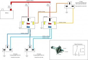
There is a diagram of how I did it, which hopefully makes sense. It purposefully isn’t a wiring schematic using auto-electrical symbols because I expect most people reading this are enthusiasts, not electricians.
Buy What You Need
First thing to get right is not to waste money on a “headlight upgrade kit” because all the bits you need are easy to obtain. I strongly recommend you visit Vehicle Wiring Products to source the stuff you need.
- 3x in-line fuse holders (or a mini fusebox)
- 1x 20Amp fuse
- 2x 15Amp fuses
- 2x 5-blade changeover relays
- 2x relay sockets
- At least 10 female crimp connectors
- Enough red 10AWG/25Amp cable to go from your battery to the relays
- Enough 12AWG/15Amp cable to go from your relays to your headlight plug (brown on my diagram)
- Same again in a different colour (Yellow on my diagram)
- Some 12AWG to earth pin 85 on each relay and third pin on each headlight to a suitable earth (eg. bodywork)
- Suitable crimp connectors to connect to your battery
- 2x H4 female sockets (these go onto the pins on your bulbs)
- 1x H4 male plug (this takes the pins from one of your existing headlight plugs)
- Enough 12AWG to run from your high (full) beam relay to each headlight (pale blue in the diagram)
- Same again but a different colour for the standard (dipped) beam
- Two blade connectors and a short length of 10AWG (see below)
- Enough corrugated plastic shielding to protect all this cable
- Enough shrink-fit insulation to do a good job protecting those crimps
- 8x bullet connectors
- 2x Double-common snap connectors
Method
The way I recommend doing it is to fit the two relays in the engine bay, attached to the bodyWork. Somewhere just ahead of the washer bottle is fine.
Run cable to each headlight to power them from pin 87 of the relays. Note: you will be running two cables from one pin, so you will have a single crimp connector, a short cable to get clear of the relay pins and then your choice of how to take it from here. I had a mountain of bullet connectors handy, so I put a female crimp on a short bit of cable with a bullet on the other end into a “double-common” bullet connector. Each cable out to a headlight was terminated on a bullet connector and just plugged in. But work out your preferred method and substitute your preferred connector types.
Take a feed from the offside headlight plug itself to pin 86 on each relay. This means you are NOT cutting into your wiring loom, so the fix is 100% removable..
Now wire-up from the battery (with the big in-line fuse in the battery compartment) and out to pin 87a on the relays (via one fuse each, near the relays). This is the fiddly bit!
Headlights now always on with sidelights
So, why are the headlights on dipped beam when you turn on the sidelights?
The answer is you have a “dim-dip” system installed. This was a legal requirement from April 1987 until 1988. Land Rover still fitted this system long after that but it is not a legal requirement any more.
All well and good, but what does that mean to us? Inside the nearside wing of your Land Rover is a chunky resister that means when the sidelight circuits are on, some current is passed through the headlights, making them run dim. But, remember we have used a feed from the headlight plug to run some relays. This “dim” voltage is still enough to trip the relays and turn the headlights on full power. We need to disable the dim-dip feature.
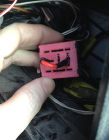
Unscrew the four screws holding on your dashboard instrument panel. Behind the jumble of wires you will see at least two relays. A Yellow one (probably YWB10027L) which stops you leaving the rear heater on when the engine is off and a pink one (YWC10050). This pink one is the troublemaker.

You can pull the relay and your lights will stop working. You can either short the socket or buy a dim-dip bypass relay. I chose to short it. You need some 25Amp cable and two spade connectors. You simply jumper between 87 and 30 as shown here:
Put the dashboard back together and now when you turn-on the sidelights, you will just get sidelights. When you tun on headlights, you will not be dragging two headlights full of current through your control stalk on the steering column.
And now you can upgrade your headlights or just be happy your stock headlights are a little bit brighter.

